Software and hardware integrated control system is a technology that realizes efficient control and management of equipment, machinery, systems or processes. This type of system is widely used in modern industrial automation, smart manufacturing, Internet of Things (IoT) and other fields. They integrate different hardware devices (such as sensors, controllers, actuators) and software systems (such as data processing, monitoring, and computing algorithms) to achieve more flexible, efficient, and precise control.
Advantages of software and hardware integrated control system
High efficiency and precise control: The integrated system of software and hardware allows precise data collection and instant analysis, thereby achieving faster and more accurate control feedback, reducing scrap rates and improving production efficiency.
Flexibility and scalability: The software modular design allows the system to be flexibly expanded according to different needs and adapted to different operating environments.
Real-time monitoring and data analysis: Equipped with real-time monitoring function, providing preventive maintenance and reducing maintenance costs and production downtime.
Remote management and control: Realize remote monitoring and control through network connection, improving operational flexibility.
cost saving: Automation reduces the need for manual operations and reduces operating costs.
Main technical introduction
Embedded system design: The embedded processor is responsible for processing real-time sensor data and driving the hardware device to perform corresponding operations.
PLC (Programmable Logic Controller): The main hardware control device in industrial automation, responsible for achieving precise mechanical control.
HMI (Human Machine Interface): Provides an interface for people to interact with the system, making operations more intuitive.
SCADA (Supervisory Control and Data Acquisition System): Used for monitoring and data collection of large industrial facilities, providing overall visual data.
Industrial Internet of Things (IIoT): Realize the connection of devices in different locations, cross-platform data synchronization and collaborative operation.
Edge computing and cloud technology: Edge computing reduces latency, and cloud technology centrally stores and analyzes data to improve system performance.
Application scope
smart factory: Production automation, process monitoring and intelligent decision-making.
Automated manufacturing: Including automated assembly lines, robotic arm control, etc.
Smart transportation: Intelligent transportation system management, traffic lights, vehicle dynamic monitoring, etc.
energy management: Optimize the operation of energy equipment and reduce energy consumption.
Medical equipment management: Operation monitoring and intelligent management of medical devices.
Future development trends
With the rapid development of artificial intelligence (AI), 5G communication and edge computing technology, software and hardware integrated control systems will develop in a direction that is smarter, more connected and more efficient. These technologies will improve the system's autonomous decision-making capabilities and enable greater interoperability, taking the automation process further in various industries.
Laser displacement sensor
1. Use of laser displacement sensor
The laser displacement sensor is a high-precision non-contact measuring device that can measure the physical properties of objects such as displacement, distance, and thickness. Usage usually includes the following steps:
Installation and fixing:Install the sensor in a stable position to ensure that the laser beam is correctly aligned with the measurement target.
Wiring and configuration:Connect the sensor's power, communication and signal output lines to the controller according to the instructions in the manual, and set the initial parameters.
Adjust the measuring range:According to the measurement requirements, set the appropriate measurement range, accuracy and laser power to ensure measurement accuracy.
2. Control methods
The control of the laser displacement sensor can be manually set through the built-in buttons of the device, or it can be automated through serial communication or PLC control.
Manual settings:Use the controls on the sensor to make range, sensitivity and filter settings.
Communication control:Use communication protocols such as RS-232C or RS-485 to transmit instructions through the controller for remote setting and parameter reading.
PLC control:Connect the sensor to the PLC and use PLC programming to control the sensor's start, stop, data reading and other operations.
3. Application of laser displacement sensor
Laser displacement sensors are widely used in various occasions of precision measurement, including:
Product testing:Test product thickness, flatness, etc. on the production line to ensure quality.
Positioning control:Used for positioning control of robotic arms and other equipment to accurately measure distance to ensure operating accuracy.
Shape measurement:Measure the surface shape of irregular objects, such as metal workpieces or electronic components, and check for surface irregularities and defects.
High-precision processing:It is used in high-precision processing of tiny components, such as the manufacturing process of microelectronics and semiconductors.
4. Simple program example (using PLC control)
The following is a simple program example for using PLC to control OMRON laser displacement sensor:
// PLC program example
// Start the sensor, read the displacement value and process it

START:
    MOV #0001, D0 // Enable sensor
    WAIT 100 // wait 100 milliseconds
    MOV D10, D1 // Store the sensor reading value in D1
    CMP D1, #0500 // Compare the displacement value to see if it meets the standard
    JUMP OK, D1 >= #0500
    MOV #0002, D0 // If not met, send a warning signal
    STOP

OK:
    MOV #0000, D0 // Stop warning
    STOP
In this program example, the PLC activates the OMRON sensor through simple instructions and continues to read values. If the measured value does not reach the expected range, the system will issue a warning signal. This control process enables automated detection and control.
Computer terminal control OMRON laser displacement sensor
1. Overview of computer control
OMRON laser displacement sensors can be controlled and acquired through a computer, making them more flexible for use in high-precision measurement, monitoring and data analysis scenarios. Using a computer to control the sensor can remotely adjust parameters and collect high-frequency data, which is suitable for the integration of automation systems and quality inspection needs.
2. Main methods of computer control
Serial communication control:The RS-232 or RS-485 communication protocols are often used, and the computer exchanges data and commands with the sensor through this connection.
USB or Ethernet connection:Some OMRON sensors support USB or Ethernet connections for fast data transfer and remote control.
Special software:The software provided by OMRON allows users to set sensor parameters, read data and monitor in real time on the computer.
Custom program control:You can use Python, LabVIEW, C++ and other programming languages to develop control interfaces and operate sensors through SDK or API.
3. Advantages of computer control
High-precision data extraction:A large amount of measurement data can be collected more quickly through the computer and analyzed in real time.
Remote monitoring and control:Operators can monitor data changes remotely and adjust measurement parameters according to the situation.
Data recording and tracking:The data is automatically stored in the computer to facilitate subsequent quality analysis or process optimization.
Multi-device connection:Allows multiple sensors to be connected to the computer at the same time for synchronous measurement and control.
4. Application examples of OMRON laser displacement sensors
Precision measurement:Used for displacement and thickness measurement of electronic components and mechanical parts.
Automated detection:Monitor the shape and size changes of items on the production line, and detect and sort unqualified products in real time.
R&D and Experimentation:It is used for material property testing in the laboratory to achieve highly accurate displacement and deformation measurements.
5. Simple control program example (Python)
The following is a Python program example to acquire data from an OMRON laser displacement sensor through serial communication.
import serial
import time

# Set up serial port connection
ser = serial.Serial('COM4', 9600, timeout=1)

#Send the command to start measurement
def start_measurement():
    ser.write(b'START\n')
    time.sleep(1)

#Read measurement data
def read_data():
    ser.write(b'READ\n')
    data = ser.readline().decode().strip()
    print("Measurement data:", data)
    return data

# Instructions to stop measurement
def stop_measurement():
    ser.write(b'STOP\n')
    time.sleep(1)

# Usage example
start_measurement()
time.sleep(2) # Wait for the measurement data to stabilize
for _ in range(5):
    read_data() # Read data 5 times
    time.sleep(0.5)
stop_measurement()
ser.close()
illustrate
In this program example,start_measurement()used to start measurement,read_data()Read the current measurement value from the sensor, whilestop_measurement()Then stop measuring. Through serial communication commands, the computer continuously collects measurement data and analyzes it.
NSK motor
1. NSK motor control method
NSK motors are widely used in industrial automation, with various control methods that vary according to motor types and application scenarios. The following are common control methods:
Open loop control:It uses basic voltage or current control to run the motor without relying on a feedback system. It is suitable for simple applications or scenarios where the load changes little.
Closed loop control:Through a feedback loop, the motor's speed and position are continuously monitored to improve accuracy. Suitable for applications requiring precise positioning and speed control.
Vector control:Using vector control technology to achieve precise control of torque and speed, it is especially suitable for applications requiring high precision and high dynamic response.
Servo control:Combining multiple controls of position, speed and current, it has the characteristics of high precision and fast response, and is suitable for high-end automation equipment.
2. Advantages of NSK motors
NSK motors offer many advantages in terms of precision, efficiency and stability, making them a popular choice in industrial automation:
High precision:NSK motors have excellent positioning accuracy, especially when using closed-loop or servo control, reaching micron-level accuracy.
Low noise and low vibration:The advanced structural design can effectively reduce noise and vibration during operation, making it suitable for sound-sensitive scenes.
High efficiency and energy saving:The motor has high energy conversion efficiency, reduces energy loss, and meets the needs of modern industry for energy conservation.
Stable and reliable:The design structure is sturdy, adaptable to harsh working environments, and has long-term operation stability.
3. Application of NSK motor
NSK motors have a wide range of applications, covering automated manufacturing, precision machining and other fields:
CNC machine tools:It is used in spindle and feed system control in CNC machine tools to provide high-precision processing positioning.
Robotics:Used for joint control of industrial robots to ensure smooth and high-precision action execution.
Semiconductor manufacturing:Used in wafer processing and handling equipment to meet ultra-precision control requirements.
Medical equipment:For example, in dental equipment and imaging equipment, it provides quiet and precise operation control.
Automated production line:Used for material handling and positioning control in automated production lines such as food and packaging.
4. Simple control program example
The following is a simple program example for using PLC to control NSK motor:
// PLC program example
// Start the motor, set the speed and acceleration, and control the running status

START:
    MOV #1000, D100 //Set the motor target speed to 1000 RPM
    MOV #200, D101 // Set acceleration to 200 RPM/s
    MOV #1, M200 // Start motor
    WAIT 500 // wait 500 milliseconds
    MOV #0, M200 // Stop motor
    STOP
illustrate
In this program example, the PLC uses simple instructions to control the NSK motor, set the target speed and acceleration, and start and stop the motor. Such a control process is suitable for simple automation control needs.
Computer terminal control NSK motor
1. Overview of computer control
Computer-side control of NSK motors is usually achieved through control software and communication protocols, which can accurately adjust the motor's speed, position and operating mode. This control method is suitable for high-precision industrial applications and scenarios requiring remote control.
2. Main methods of computer control
Serial communication control:Using RS-232, RS-485 or USB for communication, the computer can directly send instructions or parameter settings to the motor.
EtherCAT or Modbus protocol:Common in automation equipment, it allows the computer to quickly transmit instructions to multiple motors to achieve synchronous operation.
Dedicated control software:The control software provided by NSK allows users to set parameters, monitor data and diagnose faults on the motor on the computer.
Development environment control:The control interface can be developed using programming languages such as Python and C++, and the motor can be directly controlled through SDK or API.
3. Advantages of computer control
High-precision control:The computer terminal can accurately adjust the operating parameters of the motor, such as acceleration, deceleration, rotation speed, etc., achieving micron-level control accuracy.
Remote operation:Allows operators to control and monitor motors remotely, facilitating centralized management of production lines and rapid fault diagnosis.
Data recording and analysis:Operation data can be stored in the computer for further analysis and optimization.
Multi-axis collaborative control:Synchronous control of multiple motors is achieved through a computer for applications such as robotic arms that require coordinated work.
4. Application examples of computer control
Precision processing equipment:For example, CNC machine tools can control the synchronization of the spindle and feed motor to ensure machining accuracy.
Automated assembly line:Allows multiple NSK motors to work together to control every step of the production line.
Laboratory automation:In the life sciences, NSK motors are used for precise movement and measurement of samples.
5. Simple control program example (Python)
The following is an example of using Python to control an NSK motor through serial communication.
import serial
import time

# Set up serial port connection
ser = serial.Serial('COM3', 9600, timeout=1)

# Send the command to start the motor
def start_motor():
    ser.write(b'START\n')
    time.sleep(1)

# Set speed command
def set_speed(speed):
    command = f'SPEED {speed}\n'
    ser.write(command.encode())
    time.sleep(1)

# Command to stop the motor
def stop_motor():
    ser.write(b'STOP\n')
    time.sleep(1)

# Usage example
start_motor()
set_speed(1000)
time.sleep(5) # Let the motor run for 5 seconds
stop_motor()
ser.close()
illustrate
In this example, the computer connects to the NSK motor through the Python program and the serial communication port.start_motor()Used to start the motor,set_speed()Set the running speed of the motor, andstop_motor()It is used to stop the motor. This example is suitable for simple testing and control needs.
Motion control card
Definition and function
Motion Control Card is a special control hardware used to control servo motors or stepper motors. It is often used in robots, automation equipment, CNC machine tools, semiconductor equipment, etc. Its main functions include position control, speed control, interpolation operation, synchronous control, etc.
Common control methods
Position control:Precisely control the motor to move to the specified position.
Speed control:Adjust motor operating speed to match application needs.
Point to point movement:Move quickly from one point to another.
Linear/circular interpolation:Produce smooth trajectories in multi-axis applications.
Synchronous control:Start and stop multiple axes at the same time to maintain coordination.
Differences from PLC
PLC focuses on logic control and I/O processing, and is suitable for general control.
Motion control cards focus on high-precision and high-speed motion control and are suitable for precision machinery.
EtherCAT:High-speed bus supports multiple axes and has good real-time performance.
CANopen、MECHATROLINK、SSCNET:Commonly used protocols in industry.
Application scope
Automated production line
CNC machining center
3D printer
Robotic arm
Detection and positioning platform
Comparison of major brands (sorted by market share)
brand
Country
Interface type
Maximum number of control axes
feature
Global market share (estimated)
Siemens
Germany
PROFINET / EtherCAT
128 or more axes
Integrate PLC and HMI, widely used in European factories
about 15%
Mitsubishi (Mitsubishi Electric)
Japan
CC-Link / SSCNET
multi-axis
In-house PLC and driver are well integrated and have a high market share in Asia-Pacific
about 13%
Beckhoff
Germany
EtherCAT
Highly scalable
Leading the field in PC-based control, supports TwinCAT
about 12%
Yaskawa (Yaskawa Electric)
Japan
MECHATROLINK / EtherCAT
multi-axis
Complete integration of motor, servo and control, high stability
about 10%
Delta
Taiwan
EtherCAT / CANopen
More than 32 axes
Excellent integration with in-house drives, cost-effective
about 8%
Advantech (Advantech)
Taiwan
PCI / PCIe / EtherCAT
64 axes
High industrial integration capability, supports many I/O modules
about 7%
Syntec (New Generation Technology)
Taiwan
EtherCAT / PCI
64 axes
Mainly focused on machine tool applications, supporting CNC and HMI integration
about 6%
Leadshine
China
EtherCAT / CANopen / RS485
32 axes
Competitively priced, widely used in mid- to low-end equipment
about 5%
PMAC (a subsidiary of Delta)
USA
Ethernet / PCIe
128 or more axes
High-order interpolation and high-speed synchronization control
about 5%
Hiwin
Taiwan
EtherCAT / Modbus
multi-axis
Excellent integration with linear modules and driver overall solutions
about 4%
Galil Motion Control
USA
Ethernet / PCI / USB
64 or more axes
Long history, precise control, development friendly
about 3%
NSK
Japan
EtherCAT / dedicated bus
multi-axis
Excellent integration with our own direct drive motors and linear modules
about 2%
Remark
Market share data comes from market research reports and industry analyzes in recent years and is for reference only.
Actual application proportions may vary depending on region, industry and technology needs.
EtherCAT
Basic concepts
EtherCAT (Ethernet for Control Automation Technology) is a real-time industrial communication protocol based on Ethernet technology, developed by Beckhoff Automation in Germany. It has the characteristics of high speed, low delay, high synchronization, etc., and is a bus system widely used in modern industrial automation and motion control.
Main features
Good instant performance:It can achieve microsecond-level communication delay and is suitable for high-precision multi-axis synchronous control.
Supports a large number of slaves:Up to hundreds of slave stations can be connected to a single network segment.
Support Distributed Clocks:Synchronization accuracy of less than 1 microsecond can be achieved.
High packet efficiency:The master station packet can be "forwarded and processed" at each slave station without waiting for a response to be sent back.
Network topology flexibility:Supports linear, tree, star, ring and other topologies.
Topology example
Linear topology:The most common configuration is master station→slave station 1→slave station 2→slave station 3…
Ring topology:Equipped with redundant protection function, communication can be maintained even if the intermediate device is disconnected.
Application areas
Motion Control
industrial robot
Digital I/O module
Servo drives and stepper motors
Sensors and measurement systems
Common brands that support EtherCAT
Beckhoff
Delta
Yaskawa (Yaskawa Electric)
Advantech (Advantech)
Leadshine
Syntec (new generation)
Hiwin
Comparison with other industrial communications
communication protocol
Delay
synchronicity
data rate
Topology support
EtherCAT
Extremely low (<100μs)
High (supports distributed clocking)
100 Mbps
Linear, tree, circular
PROFINET
middle
Medium (requires time synchronization module)
100 Mbps
star, linear
CANopen
High(>1ms)
Low
1 Mbps
Linear
MECHATROLINK-III
Low
Middle to high
100 Mbps
Linear
Conclusion
With its high speed and high synchronization characteristics, EtherCAT has become the preferred communication protocol for modern high-performance automation systems. Especially in multi-axis motion control and real-time control applications, it has an irreplaceable position.
Galil Motor Controller
Overview
Galil is an American company specializing in the development of high-performance motion control products, providing multi-axis motor controllers, motion cards and embedded control solutions. Galil motor controllers are widely used in industrial automation, medical equipment, semiconductor manufacturing and laboratory instrumentation.
Product features
Multi-axis control:Supports servo motor or stepper motor control from 1 to 8 axes.
Various interfaces:Including Ethernet, RS232, USB, CAN and other communication methods.
Instant control:Built-in DSP controller with fast response for high-precision applications.
Programmable:Built-in DMC (Motion Control Language) supports complex logic and motion sequences.
Servo motor control:Supports various encoders and high-frequency update loops with high accuracy.
Stepper motor control:Suitable for low-cost, high-resolution positioning applications.
Hybrid control:A single controller can control both servo and stepper motors.
Common product series
DMC-40x0 Series:High-performance multi-axis Ethernet controller, supporting up to 8 axes.
DMC-3x01x Series:Compact stand-alone controller with USB and serial interfaces.
RIO series:Remote I/O device, supporting I/O expansion and PLC functions.
AMP series:Built-in motor driver controller saves space and wiring.
Application areas
Automated production line
Laser cutting and CNC machining
medical imaging scanner
Laboratory automation equipment
Robotic arm and precision positioning platform
advantage
The control accuracy is high and supports sub-micron positioning.
Excellent stability and reliability, suitable for long-term operation.
Rich development tools and technical support.
High elasticity, suitable for diverse applications.
Software and development
GalilTools:Official graphical configuration and debugging software.
DMC language:A concise and efficient motion control language for writing control programs.
API support:Provides development interfaces such as C/C++, .NET, LabVIEW, and Python.
Shopping advice
Select the corresponding product based on the number of axes and control type.
Consider whether you need an internal driver or an external driver.
Confirm the compatibility of the communication interface with existing equipment.
Evaluate future scalability and I/O needs.
Human Machine Interface (HMI)
definition
Human-Machine Interface (HMI) is an interactive platform between operators and machinery or automation systems. It allows users to monitor, control and set industrial equipment or production processes through graphical interfaces, buttons, touch screens, etc.
Main functions
Real-time data display
Device control and command input
Alarm prompts and event recording
System status monitoring and visual operation interface
Historical data query and report output
Application scenarios
Industrial automation production line
Energy and Utility Control Systems
Transportation and Building Automation
Food processing and packaging machinery
Common types
Embedded HMI (installed on the machine)
PC type HMI (using industrial computer)
Mobile device HMI (via tablet or mobile phone)
advantage
Improve operational efficiency and safety
Simplify control process and parameter settings
Immediate fault response and alarm prompts
Improve personnel’s visual understanding of equipment
challenge
Interface design must conform to user habits
Integration Complexity with PLC and SCADA
Need to prevent misuse and information security risks
Compatibility issues between different equipment manufacturers
PLC
What is PLC
PLC, whose full name is Programmable Logic Controller, is a digital electronic device specially designed for industrial environments and used to automatically control various types of machinery or production processes.
PLC functions
Logic control: perform logical operations, such as AND gates, OR gates, NOT gates, etc.
Sequence control: execute sequence control according to the set program.
Counting and timing: implement counter and time control functions.
Analog processing: monitor and control analog signals, such as temperature, pressure, etc.
PLC structure
Central Processing Unit (CPU): Responsible for executing programs and processing data.
Memory: stores programs and operating data.
Input/output module: receives external signals and controls external devices.
Power supply: Provides the electrical energy required by the entire system.
Application scope of PLC
PLC is widely used in manufacturing, automated production lines, machinery and equipment, transportation, energy management and other fields. For example:
Factory automation control system
elevator control
traffic light system
Energy monitoring and management
MITSUBISHI MELSEC PLC
Mitsubishi Electric's MELSEC PLC
series is an advanced programmable logic controller for industrial automation, capable of efficient control and management of a variety of equipment. It is widely used in manufacturing, energy management, building control and automated operation of machinery and equipment.
1. Main features of MELSEC PLC
Modular design: MELSEC PLC supports modular architecture, allowing users to add I/O modules, communication modules and function expansion modules according to needs to flexibly configure the system.
High speed processing capability: Equipped with a powerful processor with high-speed processing capabilities to ensure precise and fast control between devices.
Stable and reliable: Rugged design with excellent anti-interference and durability, suitable for working in harsh environments.
Diverse communication protocol support: Supports multiple communication protocols, such as Ethernet, CC-Link, and MODBUS, to facilitate integration with other automation equipment.
2. Main series of MELSEC PLC
FX series: Suitable for small automation systems and suitable for simple applications.
L series: It has scalability and flexibility and is suitable for small and medium-sized automation systems.
Q series: For large-scale systems, it provides stronger processing capabilities and modular expansion, and is suitable for complex applications.
iQ-R series: The latest high-end PLC series with higher performance and security for Industry 4.0 and IoT applications.
3. Application scope of MELSEC PLC
Manufacturing Automation: Such as precise control of assembly lines and packaging equipment.
energy management: Monitor and control energy facilities such as power plants and substations.
Mechanical equipment control: Suitable for automatic control of various industrial machinery.
Smart building management: Control HVAC, lighting and security systems to improve building operational efficiency.
4. MELSEC PLC programming tools
Mitsubishi MELSEC PLC uses professional programming software such as GX Works2 and GX Works3, and supports a variety of programming languages, including:
Ladder Diagram (LD)
Instruction List (IL)
Structured Text (ST)
Function Block Diagram (FBD)
These tools provide intuitive graphical programming interfaces and rich function libraries to help users quickly complete automated program development.
5. Advantages of Mitsubishi MELSEC PLC
High efficiency: With fast processing, low latency and multi-tasking capabilities, it is suitable for high-demand industrial automation applications.
Flexible scalability: Modular design allows the system to be flexibly configured and expanded according to needs.
Strong stability: Supports continuous operation of industrial applications and is suitable for long-term work in harsh environments.
Mitsubishi MELSEC PLC series is efficient, stable and flexible, capable of meeting a variety of automation needs and is a reliable choice in the field of industrial automation.
Protocol and example for communication between MELSEC PLC and computer
Mitsubishi MELSEC PLC supports multiple communication protocols to communicate with computers or other devices. These protocols allow PLC to exchange data and transmit control commands with industrial networks, SCADA systems, and monitoring computers.
1. MELSEC PLC common communication protocols
MC Protocol (MELSEC Communication Protocol): MELSEC's exclusive protocol provides data transmission between the computer and PLC.
MODBUS: A standard protocol widely used in industrial automation, supporting both RTU and TCP modes to facilitate communication between PLC and other devices or software.
CC-Link IE: A high-performance protocol based on Ethernet for efficient, low-latency data transmission, suitable for real-time control applications.
Ethernet/IP: A common industrial Ethernet protocol suitable for multi-vendor equipment interconnection.
2. Communication example between MELSEC PLC and computer
Example 1: TCP/IP communication under MC protocol
In this example, the computer uses TCP/IP to communicate with the MELSEC PLC through the MC protocol and reads the data registers in the PLC.
# Python sample code, using socket suite to communicate with MELSEC PLC
import socket

# PLC IP and Port settings
plc_ip = '192.168.1.100'
plc_port = 5000

# Establish socket connection
client_socket = socket.socket(socket.AF_INET, socket.SOCK_STREAM)
client_socket.connect((plc_ip, plc_port))

# MC protocol read request (read D100 register)
read_command = b'\x50\x00\x00\xFF\xFF\x03\x00\x0C\x00\x10\x00\x01\x04\x00\x00\x64\x00\xA8\x00\x01\x00'

# Send request
client_socket.sendall(read_command)

#Receive response
response = client_socket.recv(1024)
print("PLC Response:", response)

# Close connection
client_socket.close()
Example 2: RTU communication under MODBUS protocol
This example uses Python'spymodbusLibrary, communicates with MELSEC PLC through MODBUS RTU, and reads the register data located at 40001.
# Python sample code, using pymodbus to communicate via MODBUS RTU
from pymodbus.client.sync import ModbusSerialClient

#Set serial port parameters
client = ModbusSerialClient(method='rtu', port='/dev/ttyUSB0', baudrate=9600, timeout=1)

# Connect to PLC
client.connect()

# Read the register data at address 40001
result = client.read_holding_registers(40001, 1, unit=1)
print("Register data:", result.registers)

# Close connection
client.close()
3. Application scenarios of MELSEC PLC communication
SCADA system monitoring: Connect to SCADA system through MC protocol and MODBUS for equipment monitoring and data collection.
Device control and data exchange:Exchange data with other control systems or computers through the Ethernet/IP protocol to achieve synchronous control between industrial automation equipment.
Remote monitoring and maintenance: Use TCP/IP communication to realize remote operation and data monitoring of PLC.
Through diversified protocol support, MELSEC PLC can be flexibly applied to different industrial scenarios to achieve efficient and stable communication and data exchange.
Shihlin Electric PLC
Shihlin Electric PLC
Shihlin Electric's Programmable Logic Controller (PLC) is an industrial control device specially designed for use in automation control systems. PLC
Using digital logic for control, it can perform diverse industrial operations based on programming, such as machine control, manufacturing process management, monitoring and data collection.
Characteristics of Shihlin Electric PLC
Shihlin Electric's PLC is stable, efficient and flexible, and is suitable for various industrial scenarios. Here are its main features:
High stability:The design is rugged and durable and can withstand harsh industrial environments such as high temperature, humidity or vibration.
Modular design:Provides a variety of expansion modules, including input/output modules, communication modules, etc., which can be flexibly configured according to needs.
Programming is easy:It supports multiple programming languages and can be quickly configured and adjusted using Shilin Electric's dedicated programming software.
Strong communication skills:Supports a variety of communication protocols, such as MODBUS, RS-485, Ethernet, etc., to facilitate data transmission with other devices.
Application of Shilin Electric PLC
Shihlin Electric's PLCs are widely used in a variety of automation scenarios, including:
manufacturing:Control automated production lines and manage equipment such as robotic arms and conveyor belts.
Building control system:Used for building automation, controlling lighting, air conditioning, monitoring systems, etc.
Power management:Monitor and control power systems such as generator sets and distribution networks.
Water treatment:Control water pumps, valves and other equipment for tap water treatment and sewage treatment systems.
in conclusion
Shihlin Electric PLC has high stability and flexibility and is suitable for diverse industrial automation needs. With the development of technology, PLC has become the core equipment of modern industrial automation control, helping all walks of life improve production efficiency and control accuracy.
LabVIEW
What is LabVIEW?
LabVIEW(Laboratory Virtual Instrument Engineering Workbench) is a software developed by National Instruments
The graphical programming environment developed by the company is mainly used in measurement, data acquisition, control systems and automated testing. LabVIEW uses a visual programming interface to allow users to design programs using graphical "function blocks" without writing traditional codes.
Features of LabVIEW
LabVIEW's graphical programming approach makes it particularly suitable for engineering and scientific fields that require rapid development and testing of prototypes. Here are a few key features of LabVIEW:
Graphical programming:LabVIEW adopts the graphical programming method of data flow, allowing users to design program flows intuitively.
Built-in data retrieval:LabVIEW supports various data acquisition hardware to facilitate direct collection and processing of experimental data.
Rich function library:LabVIEW provides a large number of ready-made functions for signal processing, analysis, control, and data visualization.
Cross-platform support:LabVIEW runs on Windows, macOS, and Linux systems and supports a variety of hardware devices.
Application scope of LabVIEW
Automated testing:LabVIEW is often used to design and execute automated testing systems to improve testing efficiency and data accuracy.
Machine control:LabVIEW can be used for real-time monitoring and control of machines and equipment, such as factory automation and robotic arm control.
Data acquisition and analysis:LabVIEW supports a variety of data acquisition hardware and can quickly collect and analyze various experimental and engineering data.
Scientific research:LabVIEW can be used for rapid processing and analysis of experimental data, and is commonly used in scientific fields such as physics, chemistry, and biology.
Advantages and Challenges of LabVIEW
The advantage of LabVIEW lies in its simple graphical programming method and rich ready-to-use tools, which make it excellent in rapid development and prototyping. However, due to its high learning curve and high price of the commercial version, small and medium-sized enterprises and beginners may face challenges in terms of cost and usage threshold.
embedded system
Definition and characteristics
An embedded system is a specialized computing system that combines hardware and software to perform specific tasks. Compared with general-purpose computers, it has the following characteristics:
Highly integrated: Hardware and software are closely integrated and optimized for specific applications.
Resource constrained: usually limited by memory, processing power, and energy consumption.
High reliability: The design must ensure that the system is stable and reliable under long-term operation.
Application areas
Embedded systems are widely used in the following fields:
Household electronic products: such as smart TVs, washing machines, microwave ovens, etc.
Automotive electronics: such as anti-lock braking system (ABS), engine control unit (ECU).
Medical equipment: such as heart rhythm regulators and medical monitoring equipment.
Industrial control: such as robotic arms and industrial automation controllers.
Communication equipment: such as routers, switches, and smartphones.
components
Embedded systems mainly consist of the following parts:
Microprocessor or microcontroller: Responsible for processing operations and instruction execution.
Memory: including flash memory (Flash) and random access memory (RAM).
Input/output interface: used to receive and transmit signals, such as buttons, screens, or sensors.
Software: includes firmware and applications used to control system functions.
Future development trends
Embedded systems will develop in the following directions in the future:
The combination of artificial intelligence and machine learning enables more intelligent applications.
The popularity of the Internet of Things (IoT) has improved the connectivity between devices.
Low power consumption design and further improvement of energy efficiency.
The promotion of open source software and hardware lowers the development threshold.
Common development platforms for embedded systems
Microcontroller (MCU) Platform
Microcontroller is one of the cores of embedded systems. Common development platforms include:
Arduino:An entry-level development platform that supports a variety of sensors and modules.
STM32:Based on ARM Cortex-M core, suitable for high-performance applications.
TI MSP430:Microcontroller platform focused on low-power applications.
MCS-51:8-bit single-chip microcomputer. Among them, 8051 has been popular for many years.
Embedded Linux platform
Using Linux system as the embedded platform of the operating system, common choices are:
Raspberry Pi:Widely used in education and rapid prototyping.
BeagleBone:Suitable for industrial applications and provides rich I/O interfaces.
Intel NUC:Suitable for high-performance embedded applications.
RTOS (real-time operating system) platform
Real-time operating systems are often used in applications that require high real-time performance. The main platforms include:
FreeRTOS:Open source and lightweight, suitable for resource-constrained systems.
Zephyr OS:Designed specifically for the Internet of Things and supporting multiple hardware architectures.
VxWorks:Industrial grade RTOS, used in aerospace and medical fields.
Dedicated development platform
Application-specific embedded development platforms include:
ESP32:Built-in Wi-Fi and Bluetooth functions, suitable for IoT applications.
NVIDIA Jetson:A high-performance platform focusing on AI and image processing.
Texas Instruments LaunchPad:Supports a variety of modules, suitable for analog and digital control systems.
Software and hardware collaboration tools
When developing embedded systems, you usually need the support of the following tools:
IDEs:Such as Keil, Eclipse, Visual Studio Code.
Debugging tools:Such as JTAG, SWD (serial wire debugging) tools.
Emulators and virtual machines:For example, QEMU is used to simulate the hardware environment.
Arduino
Arduino is an open source hardware and software platform suitable for beginners and professional developers to create various electronic projects.
Arduino hardware
Arduino hardware consists of microcontrollers (such as ATmega328, ESP32, etc.) and a variety of I/O interfaces for connecting sensors, actuators, and other electronic components.
Common Arduino boards
Arduino Uno - The most commonly used starter board, suitable for beginners.
Arduino Nano - A smaller board suitable for projects with limited space.
Arduino Mega - has more I/O interfaces and is suitable for large projects.
ESP8266 / ESP32 - Supports Wi-Fi and Bluetooth, suitable for Internet of Things (IoT) applications.
Arduino software (IDE)
Arduino uses the Arduino IDE to write and upload code. The program code is written in C/C++ syntax and has many convenient libraries.
Install Arduino IDE and start it.
Choose the correct board type (e.g. Arduino Uno).
Write the code and upload it to the Arduino board.
Arduino Applications
Arduino can be used in many areas such as automation, IoT, robotics, music installations, agricultural monitoring, etc.
Automatic Irrigation System: Use Arduino to control the water pump to automatically water based on the soil moisture sensor.
Home intelligent control: such as intelligent lighting control, security monitoring, etc.
Environmental monitoring: Monitor temperature, humidity, PM2.5 and other data through sensors.
Advantages of Arduino
The Arduino platform has the advantages of being easy to learn, low cost, and rich in community support, making it easy for beginners to get started and professional developers to conduct deeper development.
logic analyzer
Equipment introduction
A logic analyzer is an electronic test instrument used to capture and analyze the behavior of digital signals. It can help engineers diagnose digital circuit problems, check signal timing and logic status, and is suitable for hardware development and troubleshooting.
Working principle
Logic analyzers are connected to digital circuits through multi-channel probes and record changes in digital signals. The device will capture the signal status according to the set timing conditions and convert the data into an easy-to-understand timing diagram or logic state table.
Main functions
Multi-channel signal analysis: multiple sets of digital signals can be monitored simultaneously.
Timing analysis: Check the time relationships between signals and identify timing issues.
Trigger condition setting: Start data capture based on specific conditions (such as signal high and low level changes).
Data storage and playback: record signal data for subsequent analysis.
Application scenarios
Logic analyzers are widely used in digital circuit design, embedded system development, communication protocol analysis and other fields. It is particularly suitable for detecting signal timing errors, verifying communication protocols, and debugging complex digital circuits.
advantage
Quickly diagnose digital signal problems and improve development efficiency.
Supports multi-channel signals and analyzes complex systems simultaneously.
The trigger function is powerful and can catch occasional problems.
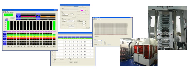
Implementation system - Yanyan performance
Solid state drive testing software
definition
Solid-state drive testing software is a specialized tool used to test the performance, stability, and health of solid-state drives (SSDs), helping users ensure that the hard drive is operating under optimal conditions and prevent data loss.
Main functions
SSD testing software provides a variety of functions, including:
Performance test:Measure SSD read speed, write speed, and random access performance.
Lifetime monitoring:Check hard drive health, including remaining life and wear.
Error detection:Detect hard disk errors or other hardware issues.
Temperature monitoring:Real-time monitoring of SSD operating temperature to prevent overheating damage.
Data cleaning:Securely erase data to protect privacy or free up storage space.
test items
Common test items include:
Continuous Reading and Writing Test:Simulate large file transfer scenarios to check stability and speed.
Random reading and writing test:Test the access performance of random small files.
IOPS test:Evaluates the number of input/output operations per second.
TRIM function test:Check whether garbage collection instructions are executed correctly to maintain performance.
Application scenarios
SSD testing software is suitable for a variety of scenarios, including:
Corporate environment:Ensure the stable operation of the SSD in the server or data center.
Personal use:Check whether the SSD in the computer is performing normally.
After-sales service:Assist hard drive manufacturers in quality inspection and troubleshooting.
Advantages
Advantages of solid state drive testing software include:
Accuracy:Provide detailed and reliable test results.
Convenience:User-friendly interface makes operation easy.
Preventative:Catch problems early to avoid data loss.
Diversity:Supports SSDs of multiple brands and specifications.
future development
The future development directions of solid-state drive testing software include:
AI integration:Use artificial intelligence for more accurate fault prediction and analysis.
Cloud testing:Implement remote testing and data analysis functions.
Multi-platform support:Improve compatibility with various operating systems and devices.
Automated testing:Achieve one-click all-round testing and improve efficiency.
Solid state drive testing software: SSD performance and development testing software
SSD performance testing software, customized IOMeter, NVMe Tester, ATA command control
Optical disc production system
definition
The optical disc production system is a set of automated production equipment used to manufacture optical discs (such as CDs, DVDs, and Blu-ray discs), covering multiple processes such as mold making, stamping molding, data burning, and label printing.
Main components
Optical disc production systems usually consist of the following parts:
Compression molding machine:The infrastructure used to manufacture optical discs.
Data burning equipment:Responsible for writing data to optical discs.
Printing equipment:Used for pattern or label printing on the surface of optical discs.
Quality control system:Test optical disc quality, such as data integrity and surface defects.
Packaging equipment:Responsible for completing the packaging of finished optical discs.
Production process
The production of optical discs usually goes through the following steps:
Make molds to ensure that the disc structure meets standards.
Compression molding produces the physical substrate of the optical disc.
Perform data burning and write the content to the disc.
Perform surface printing to add labels or patterns to optical discs.
Conduct quality inspections to screen out unqualified products.
Complete packaging and integrate the optical discs into finished products.
Application scope
Optical disc production systems are suitable for a variety of situations, including:
Music and video production:Mass production of music CDs and movie DVDs.
Data storage:Produces optical discs for backup and data distribution.
Games and software:Create installation CDs for computer games or applications.
Advantages
Advantages of optical disc production systems include:
High efficiency:Achieve large-volume automated production.
low cost:Reduce unit production costs in mass production.